1966 Plymouth Ballast Resistor Wiring Diagram
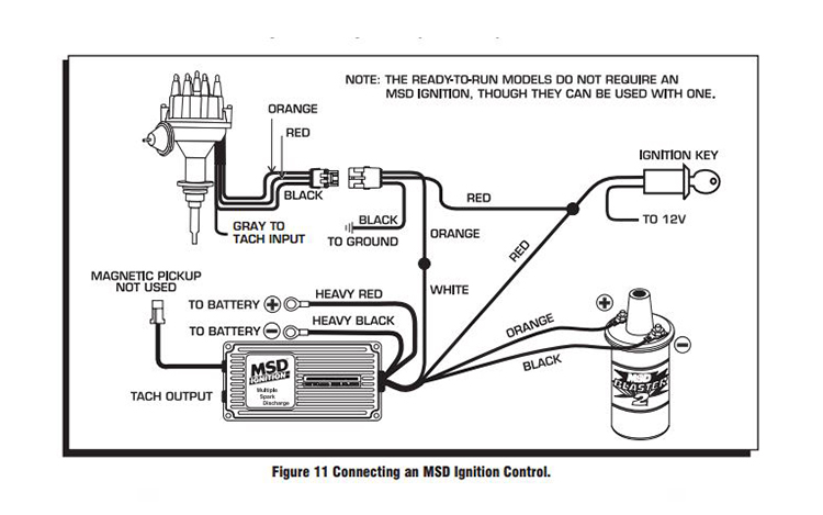
You can either splice the old coil + wire to all of it and run that wire to the msd small red, or you can pull it out and run. The diagram says the ballast resistor is not necessary.
Ballast Resistor Caused Shutdown Colonial Region Plymouth Owners Club

Diagram attached for wiring of points dizzy and coil with ballast resistor.
1966 plymouth ballast resistor wiring diagram. Oem offers the highest quality parts available. Depending on the type of installation there are two methods for ballast resistor wiring. I used to have a ballast resistor in my electrical circuit before i rewired it.
Wiring diagrams by model year wiring diagrams are sorted by model years to make it easier to find your exact diagram. 1966 valiant wiring diagrams here and here 1966 plymouth/valiant factory service manual. C body models include fury (all vari
For the most part, each year's plymouth diagram is unique to that year only after 1951. Discussion in 1960 1966 started by ol betsy dec 20 2006. This wiring diagram is for the 1980 and later four pin ignition module.
These directions will be easy to understand and use. 1972 model year 1972 chrysler 300 new yorker schematic a. Do not reconnect the wires.
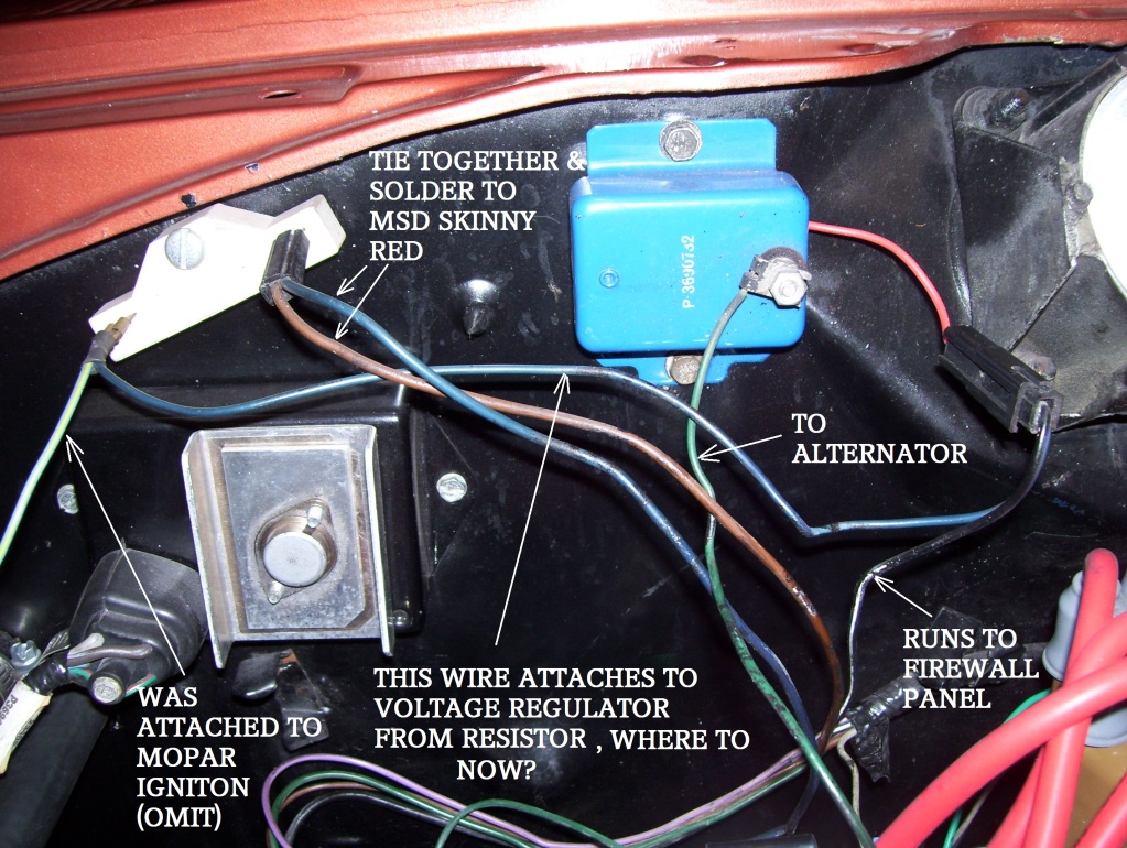
Diagram wiring diagram ballast resistor ignition coil full version hd quality. I suggest working with the electronic ignition. So, do i just solder the two wires from the ballast resistor together?
A resistor wire or ballast resistor may or may not be included in the original equipment. 12 or 14 vs 12 v needing only 16 or 18 gauge. The ballast resistor is commonly found in older vehicles, because they did not have the benefit of circuit boards found in most of today’s vehicles.
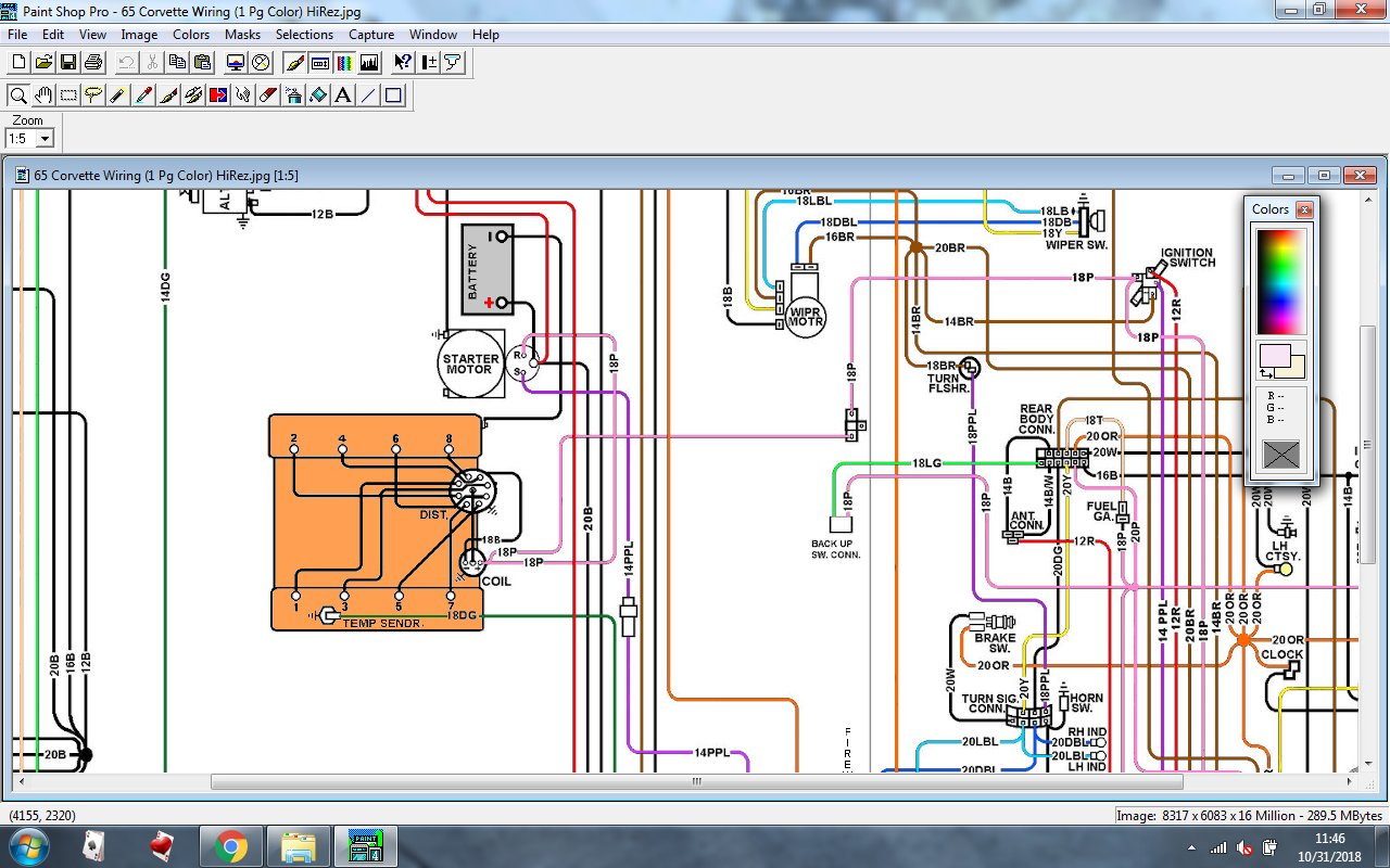
The wiring diagram shows 2 dark blue tracer wires at the round connector at the instrument panel. Prolonging point life was the. Of course i got to do the timing and stuff.
Route the blue wire to the ballast resistor. The other dark blue tracer wire goes to an under dash connector with 6 pins. A resistor that has the property of increasing in resistance as current flowing through it increases and decreasing in resistance as current decreases.
I've been using the wiring diagrams. Shows the brown wire and the coil wire connected to the other terminal of the resister. Connect one side of the.
Remove the old ballast resistor and install the new ballast resistor in its place. I had tried to post on this earlier as in volts x amps = power so for the same power requirement, 6 v will need more amps and therefore a thicker gauge wire, e.g. 1966 pontiac lemans tempest & gto color wiring diagram.
With vehicle systems becoming more and more complex, electronic components and sensors must be manufactured to precise. The typical automotive ignition system prior to 1974 consisted of a coil and ballast resistor with breaker points to interrupt the current flow when a spark was needed. Ignition coil ballast resistor wiring diagram with ignition coil ballast resistor wiring diagram, image size 609 x 360 px, and to view image details please click the image.
The ballast resistor should be mounted in a solid location either near the ecu or on the firewall. If you want to eliminate the wiring, you need to carefully cut / unwrap the harness, and pull the wiring out which went to the distributor, to the ecu, and to the ballast. This simple system is easy for even the novice mechanic to wire.
Here is a picture gallery about ignition coil ballast resistor wiring diagram complete with the description of the image, please find the image you need. These early ballasted coils are known as 12 volt coils. Installing the mopar electronic ignition requires a distributor with the magnetic pickup, and one more wire to the ballast resistor.
Over time, the ballast resistor can be damaged by normal wear and tear, so there are a few things to look for when you suspect a bad or failing ballast resistor needs servicing. Other than that i think all else looks pretty easy. The 1967 wiring diagram does show a bypass, but it does not go anywhere near the ballast resistor.
This wiring diagram is for the 1980 and later four pin ignition module. Mopar wiring diagrams 1966 to 1971. If you want points and a ballast resistor you'll need to buy them.
Avoid the exhaust manifolds and sharp edges, follow existing wiring harnesses if possible. Brown wire coming from the ign 2 ignition switch terminal. The tracer wire goes to the ign terminal.
But, this is a stock 440; A body models include valiant, duster and 1964 through 1969 barracuda. 1955 to 1959 1960 to 1965 1966 to 1971 1972 to 1976.
Let me know what you think. Disconnect the wires from both ends of the original ballast resistor. I didn't see anything like a ballast resistor but it could be under the dash.
I ran the actual wire behind it to make it look like it was still in the circuit. The ballast resistor is shown in the '57 diagrams. If you have an ignition harness with five wires, just don’t connect the dark green wire that would go to pin 3.
Strip 12 inch of insulation from each end of this wire and crimp a connector onto each end. I am planning to replace the distributor with a mallory unilite pointless distributor the instructions emphasize the necessity of either a ballast resistor or a loom resistance wire between the ignition switch and the coil. Home › 1966 pontiac lemans tempest & gto color wiring diagram.
What i'd call the feed side of the ballast resistor. But i'm only seeing one wire coming out of the side of the distributor, and i have two. Disconnect the wires from both ends of the original ballast resistor.
My car is a 65. Of the ignition switch and the solid dark blue to the voltage regulator. Take what's left and hook it together.
B body models include savoy, belvedere, gtx, satellite, roadrunner, superbird and a select few early 60's fury models. As previously identified one runs to the ignition switch. Diagram ignition with ballast resistor wiring diagram downre borgodicino it.
Plymouth fury 1966, ballast resistor by original engine management®. About that time, they went to a resistor wire, and, 12v bypass system to improve starting in cold climates.
Ford Ballast Resistor Wiring Diagram Wiring Diagram

1966 Mustang Coupe wiring Ford Mustang Forum


Mopar Electronic Ignition Wiring Diagram
1966 Dodge Monaco Ignition Wiring Mopar Forums

02B Mopar Ballast Resistor Wiring Diagram Ebook Databases

Mopar Electronic Ignition Wiring Diagram easywiring
Mopar Electronic Ignition Wiring Diagram Wiring View and Schematics Diagram

I have a 84 ramcharger. i took the body off and put on a 54 dodge pick up body on.i used most of
1966 Plymouth Valiant Wiring Diagram Wiring Library
Chrysler Ignition Wiring Diagram

Chrysler Ballast Resistor Wiring


Chrysler Ballast Resistor Wiring
No spark and i can only get 5V at the coil. For A Bodies Only Mopar Forum
Questions on voltage to the coil For B Bodies Only Classic Mopar Forum

Ballast Resistor 12 Volt Coil
1966 Mopar Ignition Wiring Diagram Wiring Diagram Schemas

☑ Dodge Ballast Resistor Wiring

'66 Corsa Ignition Problem, Need Help Identifying Wires Corvair Forum

Ignition Wiring Ballast to Coil 66 BBC CorvetteForum Chevrolet Corvette Forum Discussion